2. Features
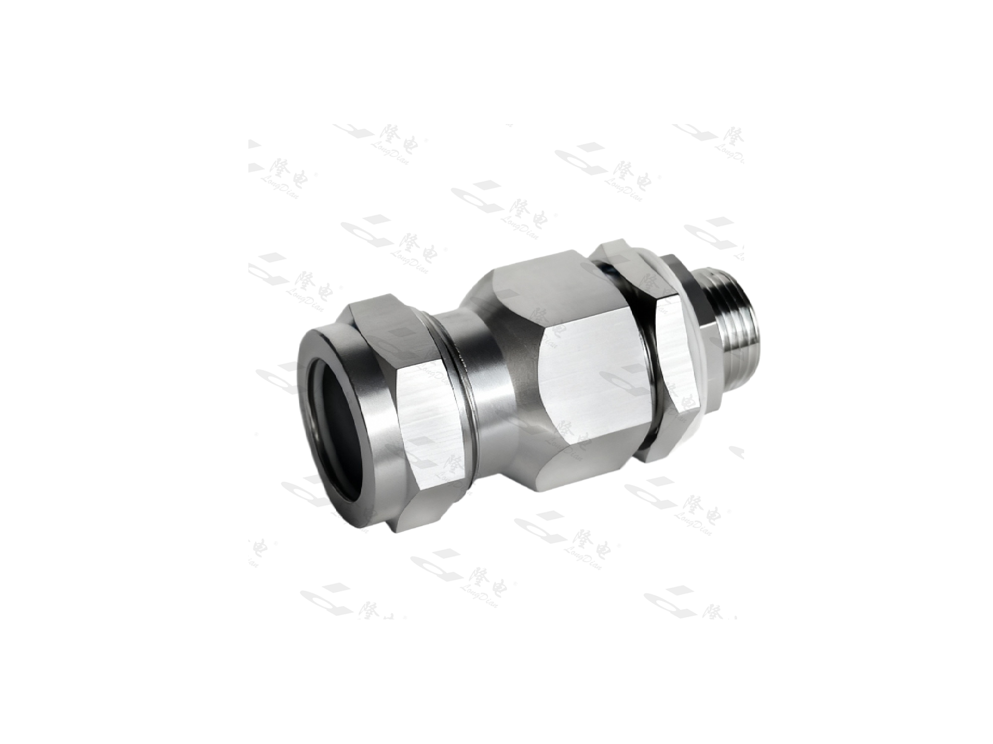
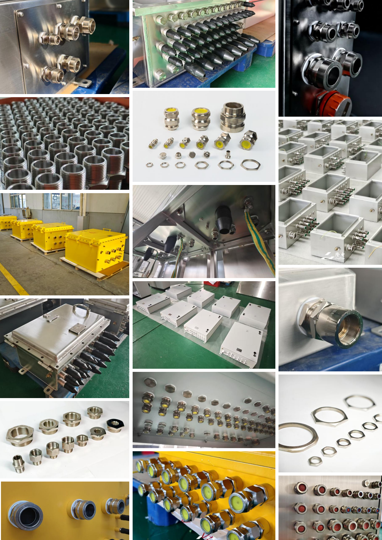
1. Ex db ⅡC Gb / Ex eb ⅡC Gb / Ex tb ⅢC Db explosion-proof certification ensures the gland effectively contains any internal ignition and prevents flame propagation to the surrounding hazardous atmosphere; IP66/IP68-rated sealing with optional rubber, neoprene, or silicone gaskets provides excellent waterproof and dustproof performance.
2. Corrosion and salt-spray resistant body materials (nickel-plated brass, SS304, SS316L) combined with Nylon 6 anti-rotation washers deliver strong mechanical structure, reliable sealing, and long service life in harsh industrial conditions; easy installation with multiple thread options (Metric, NPT, G, PG) supports flexible wiring configurations.
3. Fully customizable to meet specific project requirements — thread type, size, body material, and seal material can all be tailored; compatible with standard atmospheric pressure (80–110 kPa) and installation altitudes up to 2500 m, with a wide operating temperature range of –55 °C to +135 °C ensuring adaptability across diverse on-site conditions.
3. Related Parameter
|
Spec
|
Thread standard D
|
(mm)
Min thread
length L
|
A
(mm)
|
(mm)
Seal range to cable dia B
|
(mm)
Armour wire dia C
|
(mm)
Max dia F
|
| |
Metric
|
NPT
|
Metric
|
NPT
|
|
Standard Seal
min max
|
Thickened Seal
min max
|
Layered Seal
min max
|
1 Steel wire braided armor wire diameter
|
2 Corrugated steel tape armor thickness
|
|
|
DT-16-□-Ⅰ
|
M16×1.5
|
3/8〞
|
15
|
15.5
|
6.5
|
9.5 13.4
|
6.0 10.2
|
2.0 13.5
|
0.2/0.3
|
0.9/1.25
|
25.4
|
|
DT-20s-□-Ⅰ
|
M20×1.5
|
1/2〞
|
15
|
20
|
11.5
|
11.6 15.6
|
9.5 13.5
|
4.0 15.8
|
0.2/0.3
|
0.9/1.25
|
29
|
|
DT-20-□-Ⅰ
|
M20×1.5
|
1/2〞
|
15
|
20
|
13.5
|
16.5 20.6
|
13.5 17.5
|
5.0 21.0
|
0.2/0.3
|
0.9/1.25
|
34.6
|
|
DT-25-□-Ⅰ
|
M25×1.5
|
3/4〞
|
15
|
20.5
|
17.5
|
23.5 27.5
|
20.0 24.0
|
12.0 27.5
|
0.2/0.45
|
1.25/1.6
|
43.9
|
|
DT-32-□-Ⅰ
|
M32×1.5
|
1〞
|
15
|
25.5
|
24.5
|
29.5 33.9
|
26.0 30.2
|
18.0 34.0
|
0.3/0.45
|
1.6/2.0
|
55.4
|
|
DT-40-□-Ⅰ
|
M40×1.5
|
1-1/4〞
|
15
|
26
|
31.5
|
35.5 39.8
|
32.0 36.0
|
24.0 40.0
|
0.3/0.45
|
1.6/2.0
|
63.5
|
|
DT-50s-□-Ⅰ
|
M50×1.5
|
1-1/2〞
|
15
|
26.5
|
38.2
|
43.5 47.8
|
38.5 42.6
|
28.0 48.0
|
0.3/0.45
|
2.0/2.5
|
75
|
|
DT-50-□-Ⅰ
|
M50×1.5
|
2〞
|
15
|
27
|
40.0
|
49.0 53.1
|
46.0 50.2
|
33.0 53.0
|
0.3/0.45
|
2.0/2.5
|
80
|
|
DT-63s-□-Ⅰ
|
M63×1.5
|
2〞
|
15
|
27
|
50.0
|
47.6 60.0
|
52.0 56.2
|
40.0 60.0
|
0.3/0.45
|
2.5
|
90
|
|
DT-63-□-Ⅰ
|
M63×1.5
|
2-1/2〞
|
15
|
40
|
53.0
|
61.0 65.3
|
55.5 59.5
|
45.0 65.5
|
0.3/0.45
|
2.5
|
95
|
|
DT-75s-□-Ⅰ
|
M75×1.5
|
2-1/2〞
|
15
|
40
|
61.9
|
68.0 72.1
|
65.5 69.5
|
53.0 72.5
|
0.3/0.45
|
2.5
|
100
|
|
DT-75-□-Ⅰ
|
M75×1.5
|
3〞
|
16
|
41.5
|
63.8
|
73.5 79.8
|
71.5 75.6
|
60.0 80.0
|
0.3/0.45
|
2.5
|
110
|
|
DT-80-□-Ⅰ
|
M80×2
|
3〞
|
18
|
41.5
|
67.0
|
79.0 83.0
|
75.5 79.5
|
64.0 84.0
|
0.45
|
3.15
|
115
|
|
DT-90-□-Ⅰ
|
M90×2
|
3-1/2〞
|
18
|
44
|
77.0
|
89.0 93.0
|
84.5 88.7
|
74.0 93.5
|
0.45
|
3.15
|
125
|
|
DT-100-□-Ⅰ
|
M100×2
|
4〞
|
18
|
47
|
87.0
|
97.0 101.0
|
94.5 98.5
|
82.0 102.0
|
0.45
|
3.15
|
135
|
Special Notice: Use of Series 2 armor wire diameter shall be specified separately.
Installation, Use, and Maintenance:Users shall select the explosion-proof cable gland with the appropriate thread standard according to the structure and outer diameter of the incoming cable, following the requirements in Table 1. Ensure that the cable is securely clamped and properly sealed.
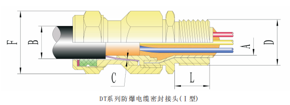
DT series explosion-proof cable gland (Ⅰ)
Assembly schematic plan for DT series explosion-proof cable gland(Ⅰ)
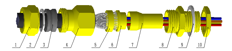
1、 seal nut
2、gasket to prevent rotating
3、rubber seal ring
4、middle body
5、ring to lock armor
6、ring seat to lock armor
7、flameproof part
8、connector
9、sealing washer
10、nut